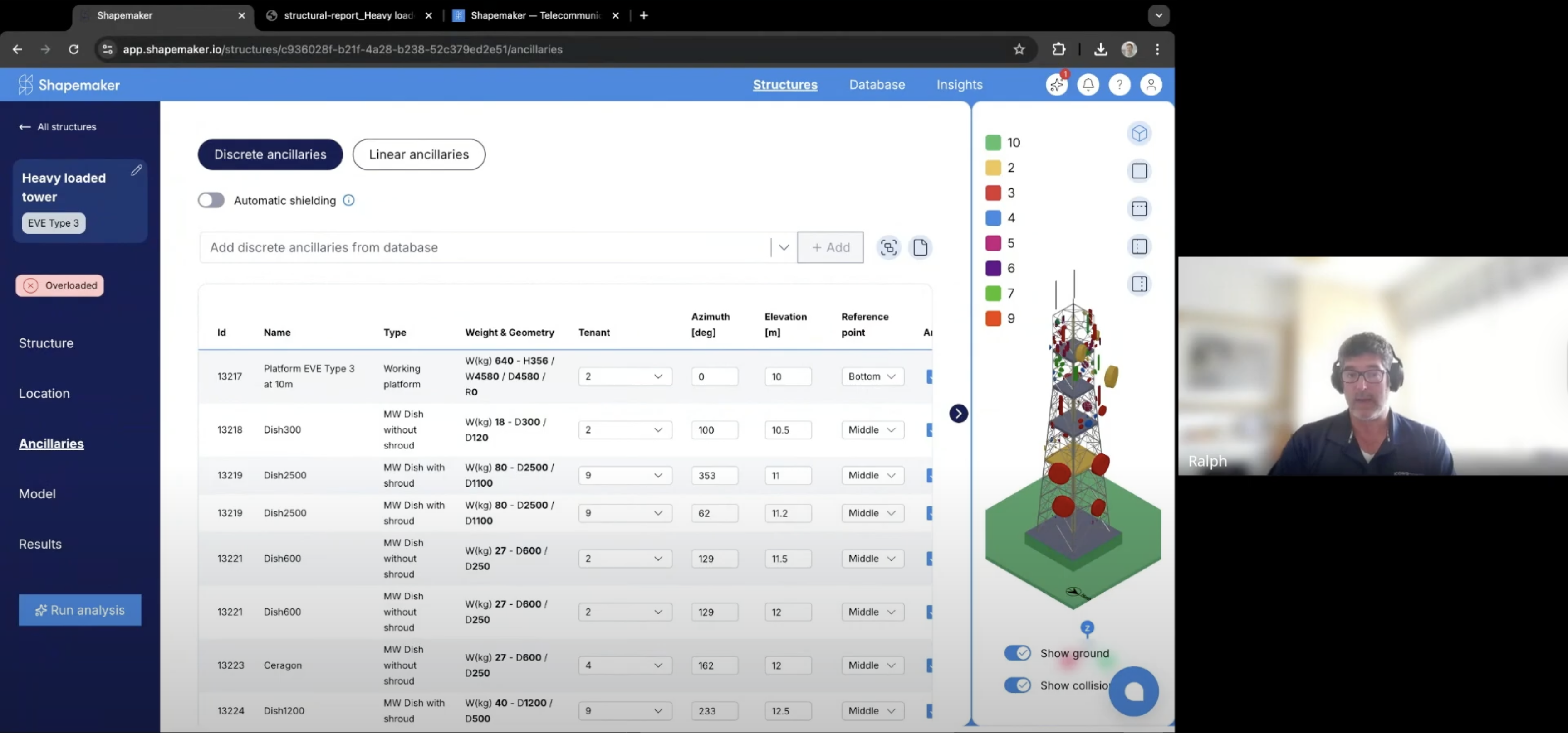
Shapemaker now lets you interactively position linear ancillaries, such as feeders or ladders, on specific tower legs and also specify custom force coefficients.
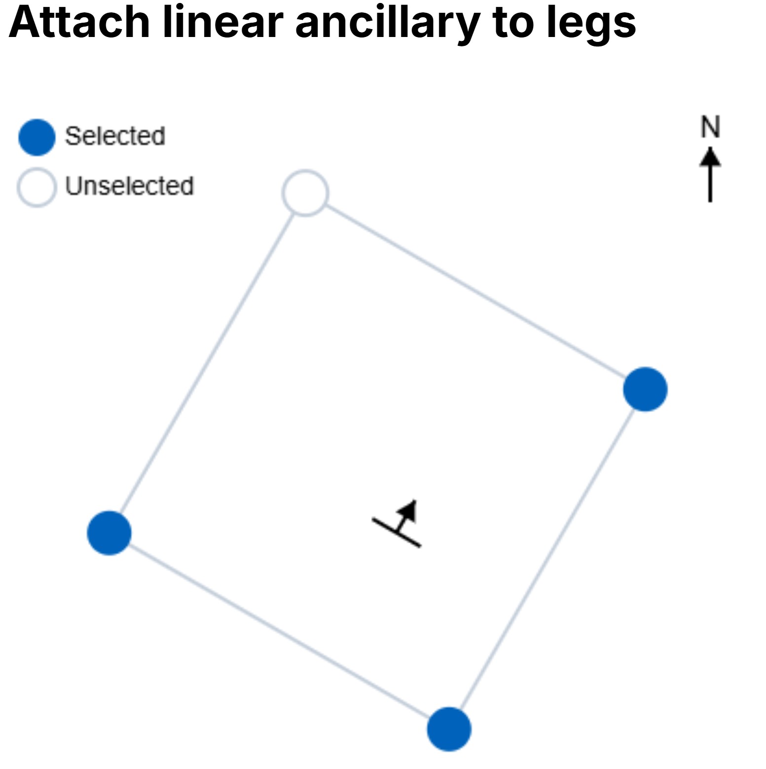
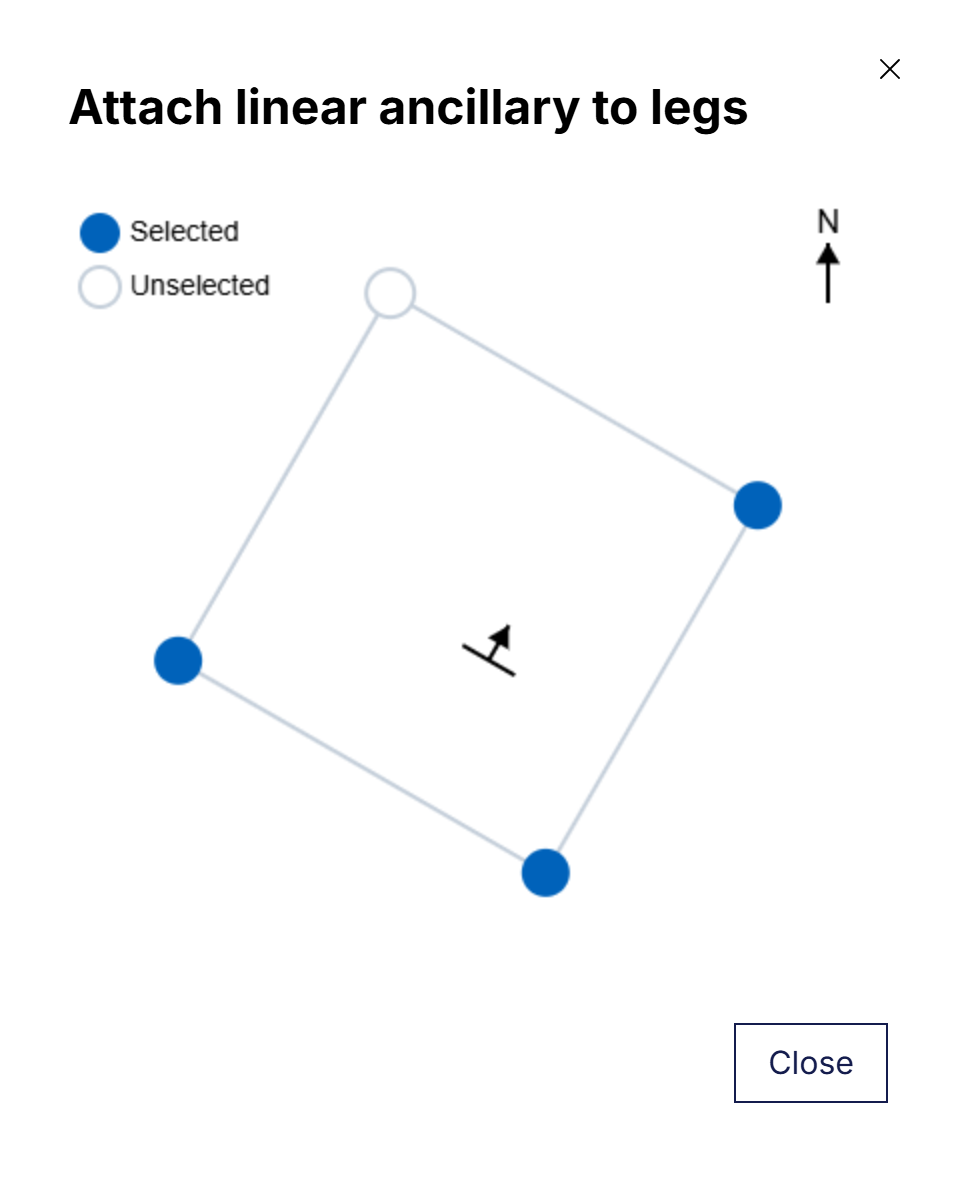
This means you can easily assign one or more lattice tower legs to each ancillary entry in just a few clicks. To help with orientation, the sketch also includes the north direction, so you always know exactly which leg(s) you’re loading.
By default, all linear ancillaries are set to load all the tower legs, meaning that the wind forces will be distributed equally to all the legs. While this is not considered conservative, it still remains a good assumption in cases where the exact position of the cables is unknown. When greater accuracy is needed and you know the exact location of your feeders or ladder, you can simply use the target button to select the legs you want to attach to. Once selected, the legs are automatically updated.

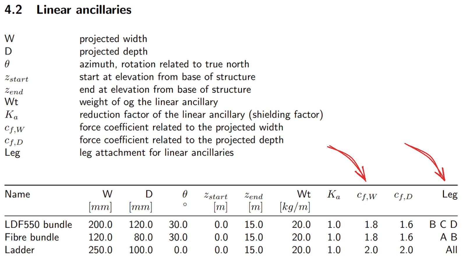
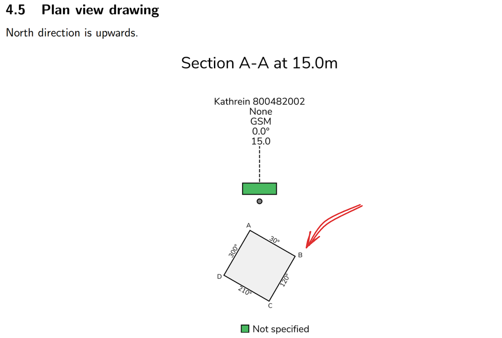
To verify that the linear ancillaries are attached to the selected tower legs, print the “Full report” and check the “Linear Ancillaries” table. Compare it with the sketches below to see which legs they are connected to.
